
Turbines 2 - Week 5 (Exam Profile - 10 Questions)
What ATA chapter is Engine Indication?
77
76
75
74
What are the two primary categories of engine instruments?
Performance Indicators & Condition Indicators
Performance Indicators & Torque Indicators
Fuel Flow Indicators & Condition Indicators
Condition Indicators & Torque Indicators
What do Performance Indicators provide?
Provide indication of the power being produced by the engine
Provide indication of the efficiency of fuel consumption by the engine
Provide indication of the overall health and condition of the engine
Provide indication of the temperature and pressure levels within the engine
What type of information do Condition Indicators display?
Display engine systems information
Display fuel consumption data
Display environmental data
Display maintenance logs
What do the Condition Indicators offer?
Offer valuable info on how hard the engine is working to produce the power displayed by the performance indicators
Offers fuel efficiency data
Offers valuable info on maintenance requirements
Offers environmental data
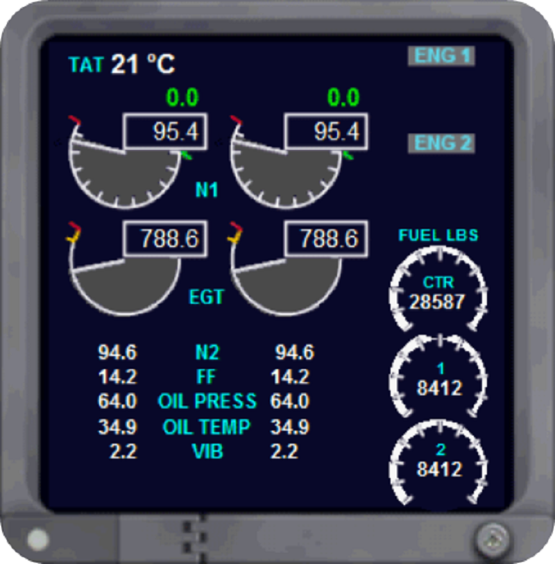
Turbojets and Turbofans' performance indicators display include what information?
Thrust indication (EPR & Fan Speed N1)
Fuel consumption (in liters per minute) and cabin temperature reading
Torque indication (Torque Oil Pressure & Torque Percentage)
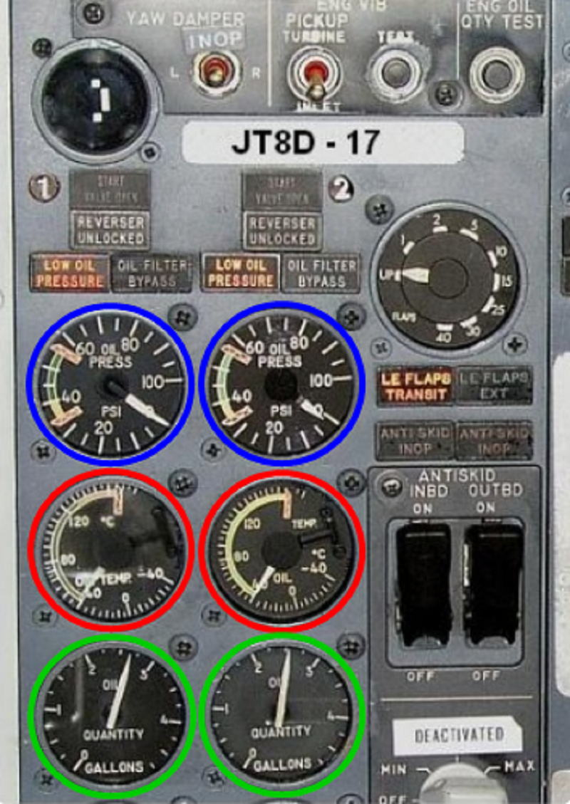
Condition indication (Engine Oil Pressure, Temperature & Quantity)

Turboprops and Turboshafts' performance indicators display include what information?
Torque indication (Torque Oil Pressure & Torque Percentage)
Fuel consumption (in liters per minute) and cabin temperature reading
Condition indication (Engine Oil Pressure, Temperature & Quantity)
Thrust indication (EPR & Fan Speed N1)
Which of the following is NOT displayed by Condition Indicators' engine systems information
Exhaust Gas Temperature & Fuel Flow
Compressor Speed (N2, N3) & Engine Vibration
Engine Oil Pressure, Temperature & Quantity
Torque Oil Pressure & Torque Percentage

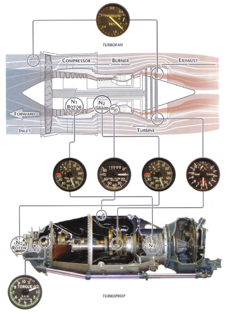
Engine Pressure Ratio (EPR) is used to measure what?
EPR is used as a measure of thrust being developed by the engine
EPR is used as a measure of torque being developed by the engine
EPR is used as a measure of fuel flow being developed by the engine
EPR is used as a measure of oil temperature being developed by the engine

What is Engine Pressure Ratio (EPR) primarily used for in turbofan and turbojet engines?
Primary thrust indicating instrument
Measuring secondary fuel consumption
Controlling primary engine speed
Monitoring secondary engine temperature
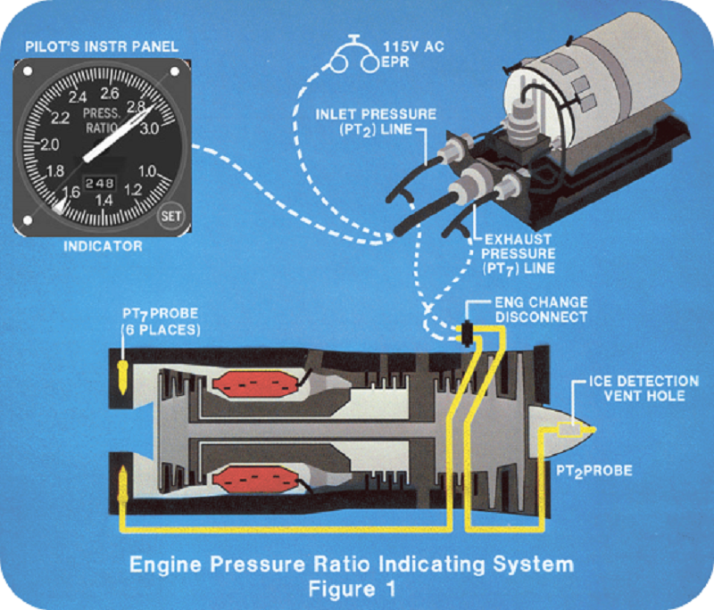
How is power indicated on the EPR display?
Power is indicated as a ratio of total exhaust gas pressure (Pt7) to total compressor inlet pressure (Pt2)
Power is indicated as a ratio of total compressor inlet pressure (Pt7) to total exhaust gas pressure (Pt2)
Power is indicated as a ratio of exhuast gas pressure (Pt7) to total turbine inlet pressure (Pt2)
Power is indicated as a ratio of turbine inlet pressure (Pt7) to total exhaust gas pressure (Pt2)
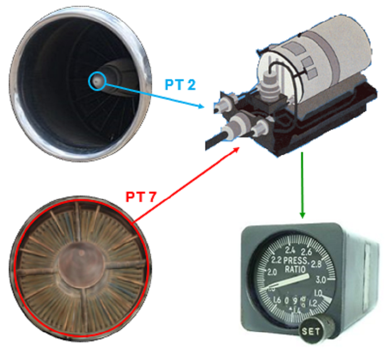
Where are the EPR pressure signals sent to?
Either an EPR transmitter (which is installed on the engine casing) or an onboard EPR computer
EPR pressure signals are not sent anywhere
Either EPR pressure gauge on the aircraft's control panel or Onboard EPR computer
Either an EPR transmitter (which is installed on the engine casing) or the hydraulic system

What does the EPR transmitter do?
Converts electrical signals to pressure inputs for display in the flight deck
Converts pressure inputs to an electrical signal for display in the flight deck
Converts temperature inputs to an electrical signal for display in the flight deck
Converts electrical signals to pressure inputs for display in the engine casing
IEPR can be found in some turbofan engines. What does the Integrated Engine Pressure Ratio (IEPR) additionally use to measure thrust?
Fan discharge pressure
Engine temperature
Compressor speed
Engine vibration
What is the primary thrust parameter used on many turbojet and turbofan engines?
N1 Speed
EGT (Exhaust Gas Temperature)
EPR (Engine Pressure Ratio)
Fuel Flow Rate
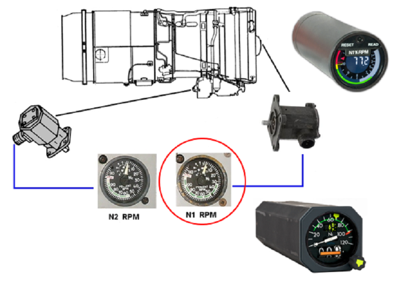
What is the role of N1 in engines that utilize an EPR system for primary thrust indication?
N1 serves as a backup for EPR system
N1 measures the exhaust gas temperature
N1 controls the fuel flow rate
N1 regulates the compressor speed
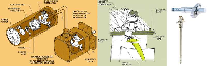
What methods are used for rotor speed sensing in the N1 system?
Tach generator & Magnetic speed sensor (variable reluctance)
Torque indicator & Compressor speed sensor (variable reluctance)
EGT indicator & Magnetoc speed sensor (variable reluctance)
Oil quantity indicator & Compressor speed sensor (variable reluctance)
Which of the following is one of two torque indication systems used on turboprop and turboshaft engines?
Torque Oil Pressure – uses a hydro-mechanical system (known as a “balanced oil piston” system)
Torque Electric Voltage - utilizes an electrical sensing mechanism
Torque Magnetic Field - relies on magnetic field variations for torque measurement
Torque Hydraulic Flow - measures torque based on hydraulic fluid flow
Which of the following is one of two torque indication systems used on turboprop and turboshaft engines?
Torque Percentage – twist of the power output shaft is converted to a torque signal (known as an electronic “phase shift” system)
Torque Electric Voltage - utilizes an electrical sensing mechanism
Torque Magnetic Field - relies on magnetic field variations for torque measurement
Torque Hydraulic Flow - measures torque based on hydraulic fluid flow

What type of system and components are used the Torque Oil Pressure system for torque indication on turboprop and turboshaft engines?
A hydromechanical (balanced oil piston) system, using helical gears
A hydromechanical (balanced oil piston) system, using hydraulic pistons
A hydromechanical (balanced oil piston) system, using magnetic fields
A hydromechanical (balanced oil piston) system, using electrical sensors
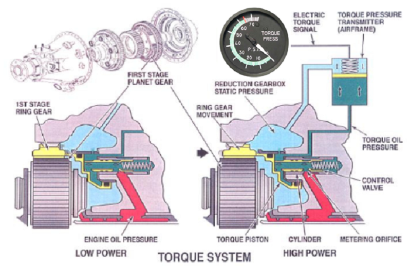
How does the hydromechanical system of Torque Oil Pressure system transfer oil?
The ring gear moves axially with an increase in torque and acts on a piston, which ports oil to the transmitter
The system utilizes electrical sensors to measure torque
Magnetic fields are used to detect torque variations
Hydraulic pistons are employed to indicate torque levels

In hydromechanical torque oil pressure system, the pressure required to resist the _____ load is transmitted to the indicator, which measures power in ______ or ______
Radial load & p.s.i. Or ft.lbs
Axial load & p.s.i. Or ft.lbs
Torsional load & p.s.i. Or ft.lbs
Shear load & p.s.i. Or ft.lbs
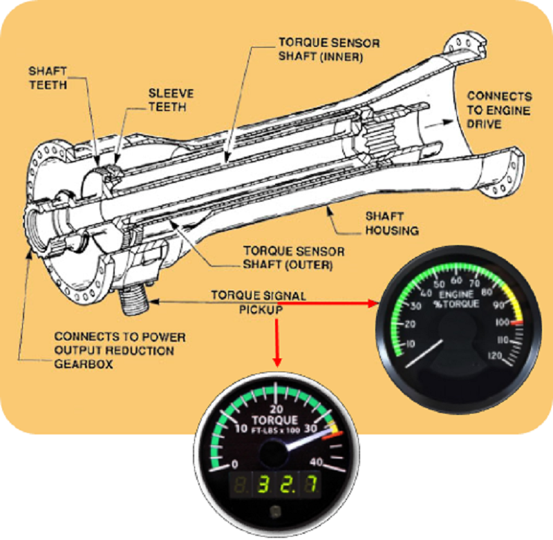
How does the Torque Percentage system of torque indication systems measure torque?
Uses magnetic pickups to measure the torsional deflection (twist) of the output shaft, which is converted into a torque signal
Uses hydraulic pressure sensors to measure the torsional deflection (twist) of the output shaft, which is converted into a torque signal
Uses optical sensors for shaft rotation to measure the torsional deflection (twist) of the output shaft, which is converted into a torque signal
Uses electrical resistance to measure the torsional deflection (twist) of the output shaft, which is converted into a torque signal
Torque percentage type of torque indication system is also known as?
Phase shift system
Torque ratio system
Torque modulation system
Torque conversion system
The more power the engine produces, the greater the twist applied to the output shaft, which is displayed as __________ on the gauge
Torque percentage (or FT-LBS)
Torque power (or p.s.i.)
Oil temperature (or F)
Oil pressure (or FT-LBS)
Which of the following is NOT a condition indicator?
0%
0

0%
0
0%
0
0%
0
0%
0
0%
0

Where are fuel flow transmitters typically located in relation to the Fuel Control Unit (FCU)?
Downstream of the FCU
Upstream of the FCU
Inside the FCU
Parallel to the FCU

What unit of measurement does the fuel flow gauge display for each engine?
Pounds or kilos per hour
Cubic feet per hour
Gallons per minute
Liters per second

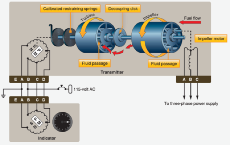
Which of the following is NOT a type of fuel flow system?
Vane type flow system
Synchronous mass flow system
Motorless mass flow systems
Gerotor type flow system

Why do many fuel flow systems also incorporate a fuel totalizer?
To display total combined fuel burn by all engines (pounds or kilos)
To measure fuel flow rate for each engine (pounds or kilos)
To calculate fuel efficiency for each engine (pounds or kilos)
To monitor fuel pressure in the fuel system (pounds or kilos)
How are density and temperature accounted for in fuel flow operation?
By measuring fuel pressure (representing mass)
By measuring fuel temperature (representing mass)
By measuring fuel viscosity (representing mass)
By measuring fuel volume flow rate

How is the inlet fuel in a fuel flow system operated?
By adjusting the impeller speed
By controlling the fuel pressure
By regulating the fuel temperature
By swirling the fuel with an impeller rotating at a fixed speed

What happens to the impeller output in a fuel flow system during operation?
It is adjusted based on fuel pressure
It is regulated by controlling the fuel temperature
Impeller output deflects a turbine just downstream, that is held with calibrated springs
Impeller output deflects a turbine just upstream, that is held with calibrated springs

Since the impeller rotates at a fixed speed during fuel flow system operation, what happens to the turbine movement?
Variations in turbine movement are caused by changes in volume or viscosity (mass)
Variations in turbine movement are caused by changes in fuel pressure
Variations in turbine movement are caused by changes in fuel temperature
Variations in turbine movement are caused by changes in fuel volume

What does Compressor Speed (Condition Indicator) display for turbojet or turbofan aircrafts?
A tach generator or magnetic speed sensor is used to display the following rotor speeds: Ng, N2 (double spool), N3 (triple spool)
A temperature sensor or fuel flow transmitter is used to display the following rotor speeds: Ng, N2 (double spool), N3 (triple spool)
A tach generator or fuel flow transmitter is used to display the following rotor speeds: Ng, N2 (double spool), N3 (triple spool)
A magnetic speed sensor or fuel flow transmitter is used to display the following rotor speeds: Ng, N2 (double spool), N3 (triple spool)
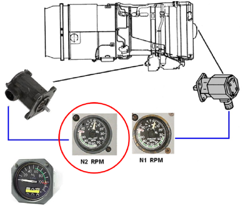
What does Compressor Speed (Condition Indicator) display for turboprop or turboshaft aircrafts?
A tach generator or magnetic speed sensor is used to display the following rotor speeds: Ng (N1) = gas turbine speed & Nf (N2) = free turbine speed
A tach generator or magnetic speed sensor is used to display the following rotor speeds: Ng, N2 (double spool), N3 (triple spool)
A temperature sensor or fuel flow transmitter is used to display the following rotor speeds: Ng, N2 (double spool), N3 (triple spool)
A tach generator or fuel flow transmitter is used to display the following rotor speeds: Ng (N1) = gas turbine speed & Nf (N2) = free turbine speed
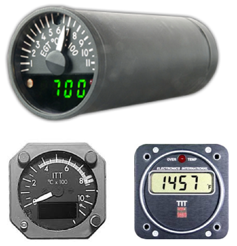
Which of the following is NOT one of three EGT systems in Condition Indicators?
Exhaust Gas Temperature (EGT) - measures the turbine outlet temperature
Inter-turbine Temperature (ITT) - measures the temperature between turbine stages
Turbine Inlet Temperature (TIT) - measures the turbine inlet temperature (usually calculated by FADEC)
Engine Pressure Ratio (EPR) - measure of thrust being developed by the engine
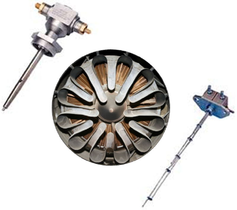
Which two metals commonly make up an exhaust gas temperature (EGT) thermocouple?
Zinc and nickel
Chrome and aluminum
Chromel and alumel
Silver and chromium
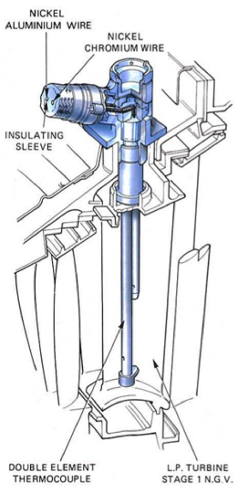
Where are thermocouples located in the EGT systems?
A series of thermocouples are placed circumferentially in the engine exhaust
A series of thermocouples are placed circumferentially in the turbine inlet
Thermocouples placed between turbine stages
Thermocouples placed between compressors

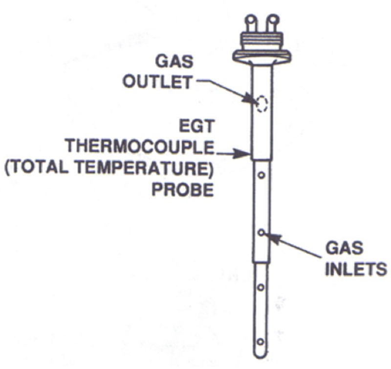
How do the thermocouples sense the temperature of the hot gases?
Each thermocouple has holes facing forward into the air stream, sensing the temperature of the hot gases (plus an exit hole facing aft)
Each thermocouple has holes through an exit hole facing aft the air stream, sensing the temperature of the hot gases (plus an exit hole facing aft)
Each thermocouple has holes through both forward-facing and aft-facing holes, sensing the temperature of the hot gases (plus an exit hole facing aft)
Each thermocouple has holes between turbine stages, sensing the temperature of the hot gases (plus an exit hole facing aft)

Thermocouple Probe Materials: Choose the distinctive feature of chromel in comparison to alumel (All given options correctly describe characteristics of chromel)
Nonferrous nickel chromium alloy
Positive (+) electrical potential
Colour-coded white
Smaller terminal connector than alumel
Which of the following is NOT an accurate characteristic of alumel (thermocouple probe material)?
Ferrous alloy of nickel aluminum
Negative (-) electrical potential
Colour-coded green
Positive (+) electrical potential
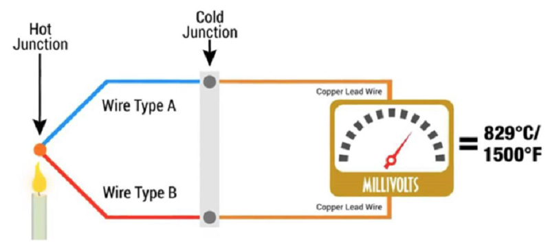
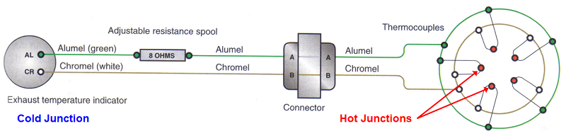
Where is the cold junction of an EGT indication system located?
At the engine connector
In the resistance spool
At the thermocouples in the engine exhaust
In the indicator (gauge)

Where is the hot junction of an EGT indication system located?
At the engine connector
In the resistance spool
In the indicator (gauge)
At the exhaust

Why is a small voltage, proportional to the applied heat, generated in EGT (Exhaust Gas Temperature) Indication Systems?
Due to the resistance of similar metals.
Because dissimilar metals conduct similarly when heat is applied
Because dissimilar metals conduct differently when heat is applied.
Because all 3 systems work functionally the same

How are the thermocouple probes in EGT (Exhaust Gas Temperature) Systems connected to each other?
The probes are connected to each other in parallel to average the temperature
They are connected in series for accurate temperature readings
All 3 systems are connected simultaneously and they are functionally the same
They are connected to the fuel flow transmitter

Why does the current flow through the cold junction when heat is applied in EGT indication systems?
Because alumel and chromel have an equal number of electrons
Because alumel has a deficiency of electrons, while chromel has an excess
Because alumel has an excess of electrons, and chromel has a deficiency
Because both alumel and chromel have a deficiency of electrons
What does the EGT indicator act as?
EGT indicator acts as an ammeter, measuring current flow
EGT indicator acts as an ammeter, It measures voltage
Measures temperature directly
Measures viscosity directly
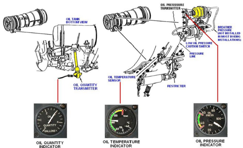
Where is Oil Quantity Transmitter located on the J8TD?
Bottom of the oil tank
Front of the oil tank
Aft of the oil tank
Top of the oil tank

How is oil pressure (Condition Indicator) information typically provided?
Information is provided by an engine-mounted oil pressure transmitter (and a pressure switch, which will generate a warning)
Information is provided by an engine-mounted temperature gauge (and a pressure switch, which will generate a warning)
Temperature sensor provides information on the operation of the oil cooler
Sender unit (transmitter) in the oil tank provides quantity information

How is oil temperature (Condition Indicator) information typically provided?
Temperature sensor provides information on the operation of the oil cooler
Information is provided by an engine-mounted oil pressure transmitter (and a pressure switch, which will generate a warning)
Information is provided by an engine-mounted temperature gauge (and a pressure switch, which will generate a warning)
Sender unit (transmitter) in the oil tank provides quantity information
How is oil quantity (Condition Indicator) information typically provided?
Sender unit (transmitter) in the oil tank provides quantity information
Temperature sensor provides information on the operation of the oil cooler
Information is provided by an engine-mounted oil pressure transmitter (and a pressure switch, which will generate a warning)
Information is provided by an engine-mounted temperature gauge (and a pressure switch, which will generate a warning)

What information does the Vibration Monitoring System (Condition Indicator) provide?
Provides indication for signs of component imbalance or looseness of parts installed on the engine
Provides indication for signs of engine temperature fluctuations of the engine
Provides fuel efficiency of the engine
Provides information on electrical output of the engine

Where and how is engine vibration sensed in the Vibration Monitoring System (Condition Indicator)?
Sensed by one or two pick-ups, called transducers, installed on the engine casing
Sensed through accelerometers attached to engine components
Sensed by pressure sensors located in the engine
Measured by inlet fuel swirled by an impeller rotating at a fixed speed
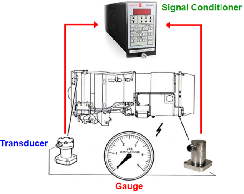
What is the principle of operation for an engine vibration transducer?
Piezo-electric effect (vibrating crystals)
Mutual indication
Electro-transformative
Electro-magnetic induction

In Vibration Monitoring System (Condition Indicator), transducers are either accelerometers or piezo-electric (vibrating) crystals that produce a _______ when a vibration is sensed
Voltage
Current
Resistance
Fuel flow

In a Vibration Monitoring System (Condition Indicator), _______ is sent to a signal conditioner, which amplifies it (also digitizes it in some cases) and provides output to the instrument for display
Voltage
Current
Resistance
Fuel flow
In the Vibration Monitoring System, where would the two transducers typically be installed if two are used?
One towards the front and one towards the back of the engine
Both towards the front of the engine
Both towards the back of the engine
One on the left side and one on the right side
What is the primary distinction in the vibrations sensed by two transducers in the Vibration Monitoring System?
The front transducer senses higher frequency vibrations, while the aft one senses lower frequency vibrations
Both transducers sense vibrations at the same frequency
The front transducer senses vibrations on the left side, while the aft one senses vibrations on the right side
The front transducer sense low frequency vibrations, while the aft one senses higher frequency vibrations
In the Flight Deck Displays, how are engine indication (instrument) displays typically divided?
Into Primary Indication & Secondary Indication (2 sections)
Into fuel efficiency and emissions sections
Into temperature and pressure sections
Into speed and altitude sections
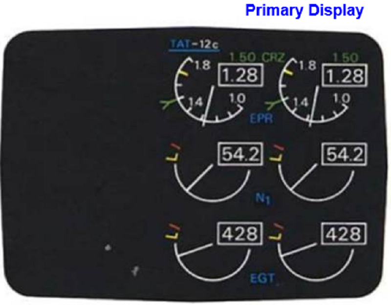
What does the Primary Indication section in Flight Deck Displays include?
Performance instruments, as well as critical parameters (such as EGT)
Secondary performance instruments
Non-critical parameters
Instruments related to fuel efficiency
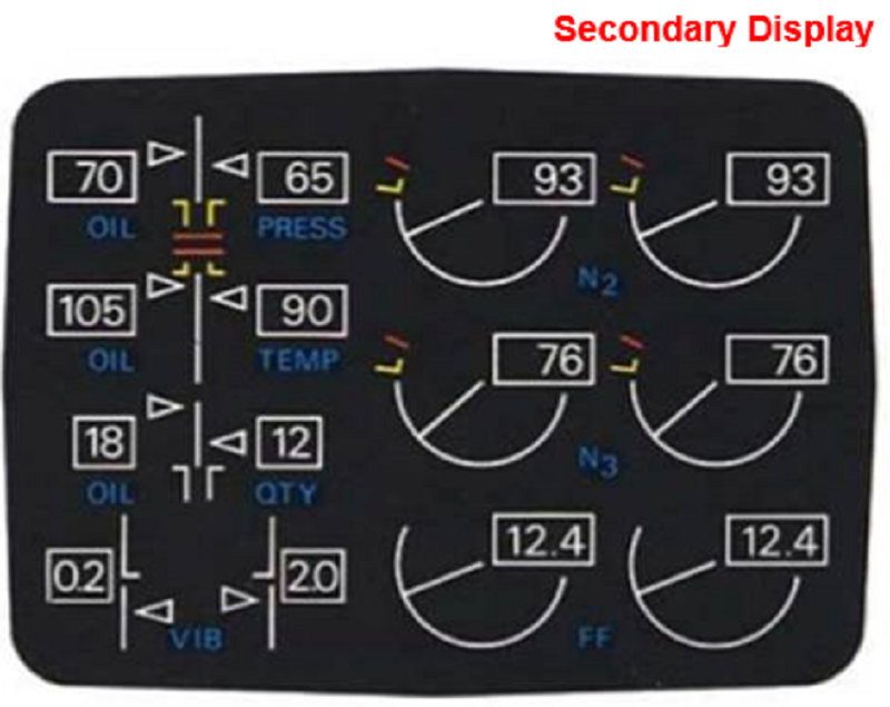
What is typically included in the Secondary Indication section in the Flight Deck Displays?
Condition instruments, such as engine oil information and engine vibration data
Primary instruments displaying speed and altitude
Non-critical parameters and fuel efficiency data
Performance instruments and critical parameters
What factor influences the appearance of the engine indication displays (Both primary and secondary) on an aircraft?
The altitude of the aircraft
The weather conditions during flight
The age and technology of the aircraft
The fuel efficiency of the engines
In the context of engine indication displays, what technology is commonly used in older aircraft compared to newer generation aircraft?
Older aircraft will use analog instrument displays
Newer generation aircraft use CRTs with digital instrument readouts
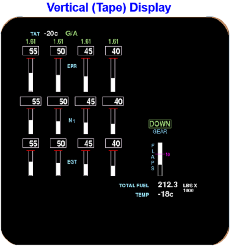
Some aircraft engine instruments are set up as a vertical (tape) display
All of the above
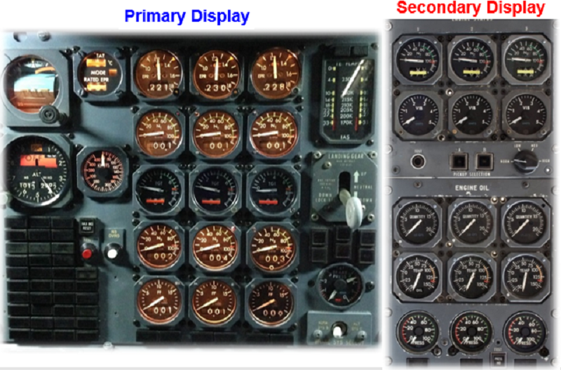
Which of the following accurately describes Analogue type of display on flight deck displays?
Used in older aircraft, primary display is on centre instrument panel and secondary is on Flight Engineer panel
Used in newer aircraft, primary display is on the left instrument panel and secondary is on Flight Engineer panel
Used in older aircraft, secondary display is on the centre instrument panel and primary is on Flight Engineer panel
Used in newer aircraft, secodary display is on the right instrument panel and primary is on Flight Engineer panel
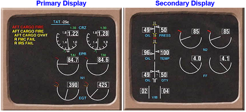
Which of the following accurately describes the Digital type of display on flight deck displays?
Used in older aircraft, both displays are on the left instrument panel
Used in newer aircraft, both displays are on the right instrument panel
Used in older aircraft, both displays are on the Flight Engineer (F/E) panel.
Used in newer aircraft, both displays are on the centre instrument panel
What happens if an engine instrument operates in the exceedance range?
The instrument is immediately replaced
The aircraft is grounded for inspection
The time (duration) is recorded, and subsequent inspections may be required
No action is taken, as it is a common occurrence
Which indication is used as a turbine performance indicator ?
N1
EPR
Torque Percentage
All of the above
Select the correct statement regarding the measurement of EGT, ITT and TIT
Digital probes are used to measure temperature
Oil is heated and the pressure is converted to a temperature for indication
Two dissimilar wires generate a voltage when heated
Exhaust heat rotates a generator that provides a proportional voltage
Which engine indication may use a tach generator or magnetic pickup for indication?
EPR
N1 speed
EGT (ITT, TIT)
Engine vibration
Identify an operating principle of a vibration transducer from the following:
Infrared thermography
Magnetic induction
Magic crystals
Piezoelectric crystals
{"name":"Turbines 2 - Week 5 (Exam Profile - 10 Questions)", "url":"https://www.quiz-maker.com/QPREVIEW","txt":"What ATA chapter is Engine Indication?, What are the two primary categories of engine instruments?, What do Performance Indicators provide?","img":"https://www.quiz-maker.com/3012/CDN/96-4695625/indicators.png?sz=1200"}