
Digital Communication Systems Quiz

Digital Communication Systems Quiz
Test your knowledge on digital signal transmission and modulation techniques with this engaging quiz! Designed for students and enthusiasts, this quiz covers various aspects of digital communication systems.
Whether you're looking to reinforce your understanding or simply challenge yourself, this quiz is perfect for you!
- 64 thought-provoking questions
- Multiple choice format
- Learn and have fun!
In digital signal transmission, -------is used to recover the data signal.
HPF
LPF
the repeater
encoder
During long haul transmission, the ------ part of the digital signal will easily attenuate.
low frequency
high frequency
analog
information
In digital communication systems, the signal has to be ------- before transmission.
encoded
modulating
decoded
modulated
In digital communication systems, ----- technique is to modulate the data signal to two different frequencies.
FSK
PSK
ASK
PCM
In FSK technique, the data signal will be recovered based on the ----- different frequencies.
five
three
two
four
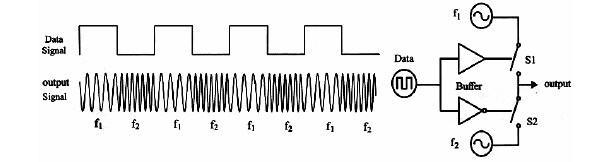
The digital transmission technique shown in Figure (1) is belongs to ------
PCM
PSK
ASK
FSK
In Figure (1), when the data signal is 5 V, after the signal pass through the buffer, the switch S1 will ------
open
closed
not connect
not operate
In Figure (1), switch S1 will closed, then the frequency of FSK signal is ------
f2 – f1
f2
f1 + f2
f1
In Figure (1), when the data signal is 5 V, after the signal pass through the buffer, the switch S2 will ------
closed
open
not connect
not operate
In Figure (1), switch S2 will closed, then the frequency of FSK signal is ------
f2 – f1
f2
f1 + f2
f1.
In Figure (1), switch S2 will opened, then the frequency of FSK signal is ------
f2 – f1
f2
f1 + f2
f1
In Figure (1), switch S1 will opened, then the frequency of FSK signal is ------
f2
f2 – f1
f1 + f2
f1.
In Figure (1), the difference between frequencies f1 and f2 has to be as ------ as possible.
small
suitable
large
big
In Figure (1), the value of f1. is ------ Hz.
1370
870
2225
1725
In Figure (1), the value of f2. is ------ Hz
870
2225
1370
1725
In Figure (1), these two frequencies can be produced by using -----
LPF
CVO
VCO
HPF
In Figure (1), the frequency gap is equal to -------
2000
1500
1000
500
In Figure (1), the output signal frequencies are varied by the difference ------ levels
voltage
current
resistance
capacitance
Varactor diode is mainly used for changing the -------- value of oscillator
resistance
inductance
capacitance
voltage
Varactor diode is a diode, which its ------- can be varied by adding a reverse bias to pn junction.
capacitance
inductance
resistance
voltage
In varactor diode, when reverse bias increases, the depletion region become -----
suitable
narrow
not suitable
wide
In varactor diode, when reverse bias decreases, the depletion region become -----
narrow
suitable
wide
not suitable
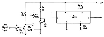
The circuit diagram shown in Figure (2) is used in --------
FSK demodulator
FSK modulator
ASK demodulator
FSK modulator
In Figure (2), the operation theory is to convert the voltage level of data signal to appropriate ------- level
resistance
current
capacitance
voltage
The circuit shown in Figure (2) is used as ------- converter.
frequency to voltage
voltage to current
voltage to frequency
capacitance
In Figure (2), the Q1, Q2, R1, R2, R3, VR1 and VR2 comprise a ----- converter
frequency
voltage
capacitance
current
In Figure (2), when Q1 switch on, Q1 is -----
switch on.
open
switch off
short
In Figure (2), Q1 will operate as ------ gate
OR
AND
XOR
NOT
In Figure (2), when the input signal of the base of Q1, is high, then Q1 will ------
switch on
open
switch off
short
In Figure (2), if VR1 = 250 kΩ, VR2 = 5kΩ, the value of V1 = ------ V
9
10
8
11
In Figure (2), if VR1 = 250 kΩ, VR2 = 5kΩ, the value of V2 = ------ V
9.865
9.789
9.254
9.967
In Figure (2), if VR1 = 250 kΩ, VR2 = 5kΩ, the value of f1 = ------ Hz
595.238
600.587
589.238
610.568
In Figure (2), if VR1 = 250 kΩ, VR2 = 5kΩ, the value of f2 = ------ Hz
598.548
610.587
605.126
565.236
In FSK modulator, the ------- level of digital signal has been converted to frequency
resistance
current
voltage
reactance
In FSK receiver, the ----- of digital signal should be converted back to voltage.
frequency
current
voltage
resistance
PLL is a kind of automatic tracking system, which is able to detect the input signal ------
reactance
resistance
voltage
frequency
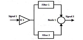
The block diagram shown in Figure (1) is ----------- detector.
PCM
asynchronous FSK
synchronous ASK
PSK
In Figure (1), the Signal 1 is a modulated -------- signal.
FSK
ASK
PSK
PCM
In Figure(1), the integrated circuit IC 1 is a --------
comparator
buffer
amplifier
encoder
In Figure (1), the Filter 1 is a -------- filter
band stop filter
HPF
LPF
BPF
In Figure (1), the central frequency of Filter 1 is equal to ------
ωC+ ωD
ωC- ωD
ωC/ ωD
ωD/ ωC
In Figure (1), the central frequency of Filter 2 is equal to ------
ωC/ ωD
ωC+ ωD
ωC- ωD
ωD/ ωC
In Figure (1), the Node 1 is a -------node.
subtracting
summing
multiplying
dividing
In Figure (1), Signal 2 is a modulating -------
PSK
PCM
ASK
FSK
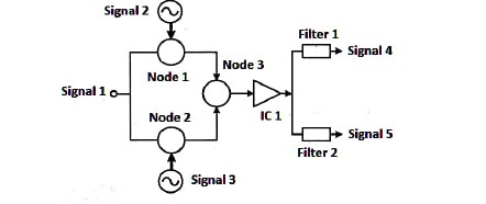
The block diagram shown in Figure (2) is a---------- detector
PSK
synchronous FSK
asynchronous FSK
PCM
In Figure (2), the Signal 1 is a modulated -------- signal.
ASK
PCM
PSK
FSK
In Figure (2), the frequency of Signal 2 is equal to ------
ωC+ ωD
ωC- ωD
2(ωC+ ωD)
2(ωC- ωD)
In Figure (2), the frequency of Signal 3 is equal to ------
2(ωC+ ωD)
2(ωC- ωD)
ωC- ωD
ωC+ ωD
In Figure (2), the Node 1 is a ------- node.
multiplying
summing
dividing
subtracting
In Figure (2), the Node 2 is a ------- node.
summing
dividing
summing
Multiplying
In Figure (2), the IC 1 is -------
encoder
amplifier
buffer
comparator
In Figure (2), the Node 3 is a ------- node.
summing
multiplying
subtracting
dividing
In Figure (2), the central frequency of Filter 1 is equal to ------
(ωC+ ωD)
2(ωC+ ωD)
2(ωC- ωD)
(ωC- ωD)
In Figure (2), the central frequency of Filter 2 is equal to ------
2(ωC- ωD)
(ωC+ ωD)
2(ωC+ ωD)
(ωC- ωD)
In Figure (2), the Filter 1 is a -------- filter
LPF
BPF
HPF
BSF
In Figure (2), the Filter 2 is a -------- filter
HPF
BSF
LPF
BPF
In Figure (2), when Signal 1 = 2cos(ωC+ ωD)t, the value of Signal 4 is ------
2cos(ωC- ωD)t
cos2(ωC- ωD)t
cos2(ωC+ ωD)t
2cos(ωC+ ωD)t
In Figure (2), when Signal 1 = 2cos(ωC+ ωD)t, the value of Signal 5 is ------
cos2(ωC+ ωD)t
2cos(ωC- ωD)t
cos2(ωC- ωD)t
2cos(ωC+ ωD)t
In Figure (3), the Block 1 has a name ------
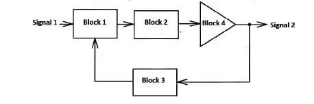
loop filter
amplifier
phase detector
VCO
In Figure (3), the Block 2 has a name ------
VCO
phase detector
amplifier
loop filter
In Figure (3), the Block 3 has a name -----
- amplifier
VCO
loop filter
phase detector
In Figure (3), the Block 4 has a name ------
loop filter
phase detector
amplifier
VCO
In Figure (3), the Signal 1 is changing with -------
phase
frequency
amplitude
voltage
In Figure (3), the Signal 2 is changing with -------
amplitude
phase
voltage
frequency
{"name":"Digital Communication Systems Quiz", "url":"https://www.quiz-maker.com/QPREVIEW","txt":"Test your knowledge on digital signal transmission and modulation techniques with this engaging quiz! Designed for students and enthusiasts, this quiz covers various aspects of digital communication systems.Whether you're looking to reinforce your understanding or simply challenge yourself, this quiz is perfect for you!64 thought-provoking questionsMultiple choice formatLearn and have fun!","img":"https:/images/course1.png"}