
Quiz (1)-Second time

Diode Experiment Quiz
Test your knowledge on diode characteristics and circuit implementations with our interactive quiz! This quiz is designed for students and enthusiasts who are exploring the fundamentals of electronics and rectifier circuits.
Join us and enhance your understanding of:
- Voltage and current relationships
- Rectifier circuit configurations
- Signal measurements and analysis
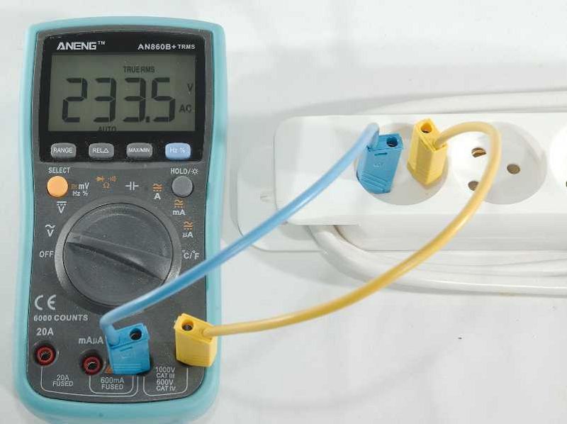
From the figure shown:
Average value of electricity = 233.5V
Peak value of electricity = 233.5V
RMS value of electricity = 165.6 V
Peak value of electricity = 329.2 V
To implement the experiment of (V I) characteristic of Diode we need:
Resistor - Regulator - capacitor - Diode - Fun
Resistor - Diode - capacitor - Fun
Resistor - Digital multimeter - Diode - Power supply
Resistor - Digital multimeter - Bridge - Power supply
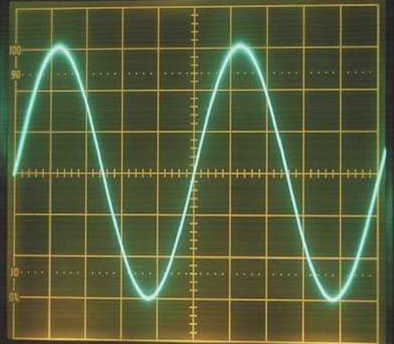
We got the signal shown in figure from the Fun
1
0.5
2
5
We can implement the HWR circuit using 1, 2,3 or 4 diodes connected in series in the same direction
True
False
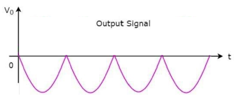
In Bridge FWR circuit, We can get the output shown in figure when we:
Invert the fun
Invert the bridge terminals
Invert the oscilloscope terminals
All of them correct
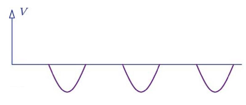
Half wave rectifier circuit that resulted the output signal shown in the figure is:
0%
0
0%
0

0%
0
0%
0
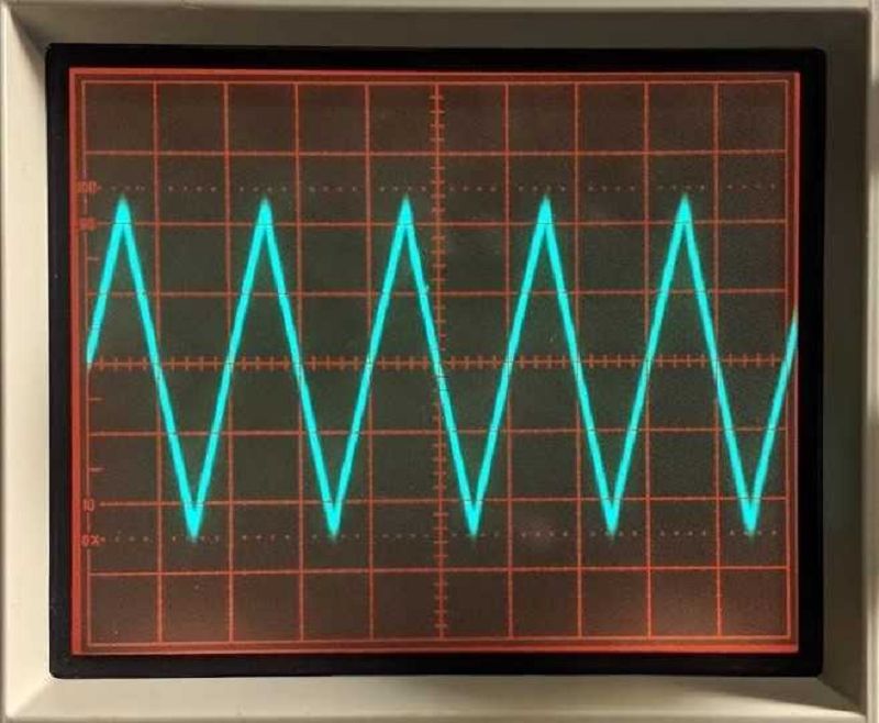
For the signal shown: If the time/div=5ms and the volt/div= 2V, then the peak to peak value of signal=
10 V
20 V
25 V
50 V
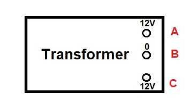
For the Transformer available in the lab, We can use terminals .................. To feed in circuits.
A and B
A and C
B and C
All answers are true
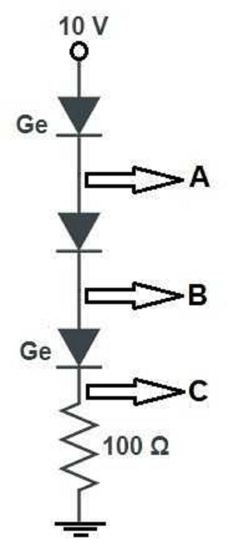
For the circuit shown: The voltage difference between point A and point C=
8.7 V
0.9 V
1 V
9 V
In the lab we consider:
Function generator is input device and Oscilloscope is output device
Function generator and Oscilloscope are output devices
Function generator and Oscilloscope are input devices
Oscilloscope is input device and Function generator is output device
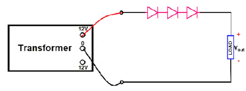
IF we connect circuit shown in the figure, the maximum peak value of output voltage will be:
9.90 V
6.39 V
14.87 V
31.84 V
The correct number of regulator taken in the lab:
8705
7805
0785
0875
In FWR circuits, The general shape of output signal is the same either we use center tap or Bridge FWR
True
False
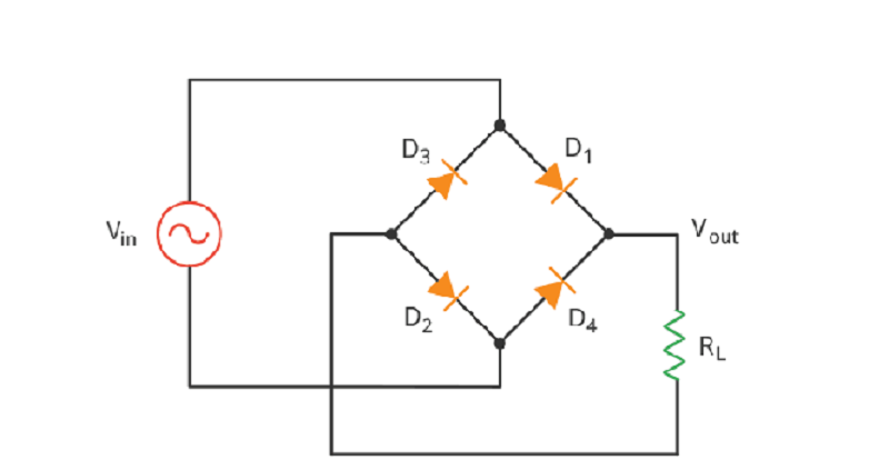
In the circuit shown. If we replace AC source with 12V DC power supply, what do you expect?
The circuit will work normally as rectifier circuit
The current will pass through D3 and D4 only
The frequency of output signal will be zero
All answers are true
In V I characteristic curve of diode experiment. Practically, there is no current passing in the circuit when the power supply be 0.4V
True
False
{"name":"Quiz (1)-Second time", "url":"https://www.quiz-maker.com/QPREVIEW","txt":"Test your knowledge on diode characteristics and circuit implementations with our interactive quiz! This quiz is designed for students and enthusiasts who are exploring the fundamentals of electronics and rectifier circuits.Join us and enhance your understanding of:Voltage and current relationshipsRectifier circuit configurationsSignal measurements and analysis","img":"https:/images/course8.png"}