Rotary Week 4 Review
What is the purpose of the tail rotor system?
To provide pitch control
To provide roll control
To provide yaw control
To increase lift
What is the purpose of the tail rotor system?
To counteract torque forces created by the engine driving the main rotor
To counteract thrust forces created by the engine driving the main rotor
To counteract lift forces created by the engine driving the main rotor
To control the teetering forces created by the engine driving the main rotor
Which of the following is NOT one of the standard requirements of the system driving the tail rotor?
Transmit rotational from the transmission to the tail rotor
Allow for flexibility at vey high rotational speeds die to loads and forces acting on the tail boom
Change the directional plane of rotation to meet the requirements for location and orientation of the tail rotor.
Allow the system to rotate independently form the main rotor transmission during in flight emergency or "hot loading" of the helicopter
Which of the following is NOT one of the standard requirements of the system driving the tail rotor?
Reduce speed of rotation to prevent supersonic tail rotor blade tip speeds
Must have its own self-contained oil pump for lubrication
Allow for flexibility at vey high rotational speeds die to loads and forces acting on the tail boom
Change the directional plane of rotation to meet the requirements for location and orientation of the tail rotor.
Which of the following is NOT one of the additional requirements of the system driving the tail rotor?
Allow for variable geometry of the tail boom
Assist in driving the main rotor during autorotation
Prevent wobbling of the loing driveshaft at high speeds
Drive additional elements to support the lubrication system
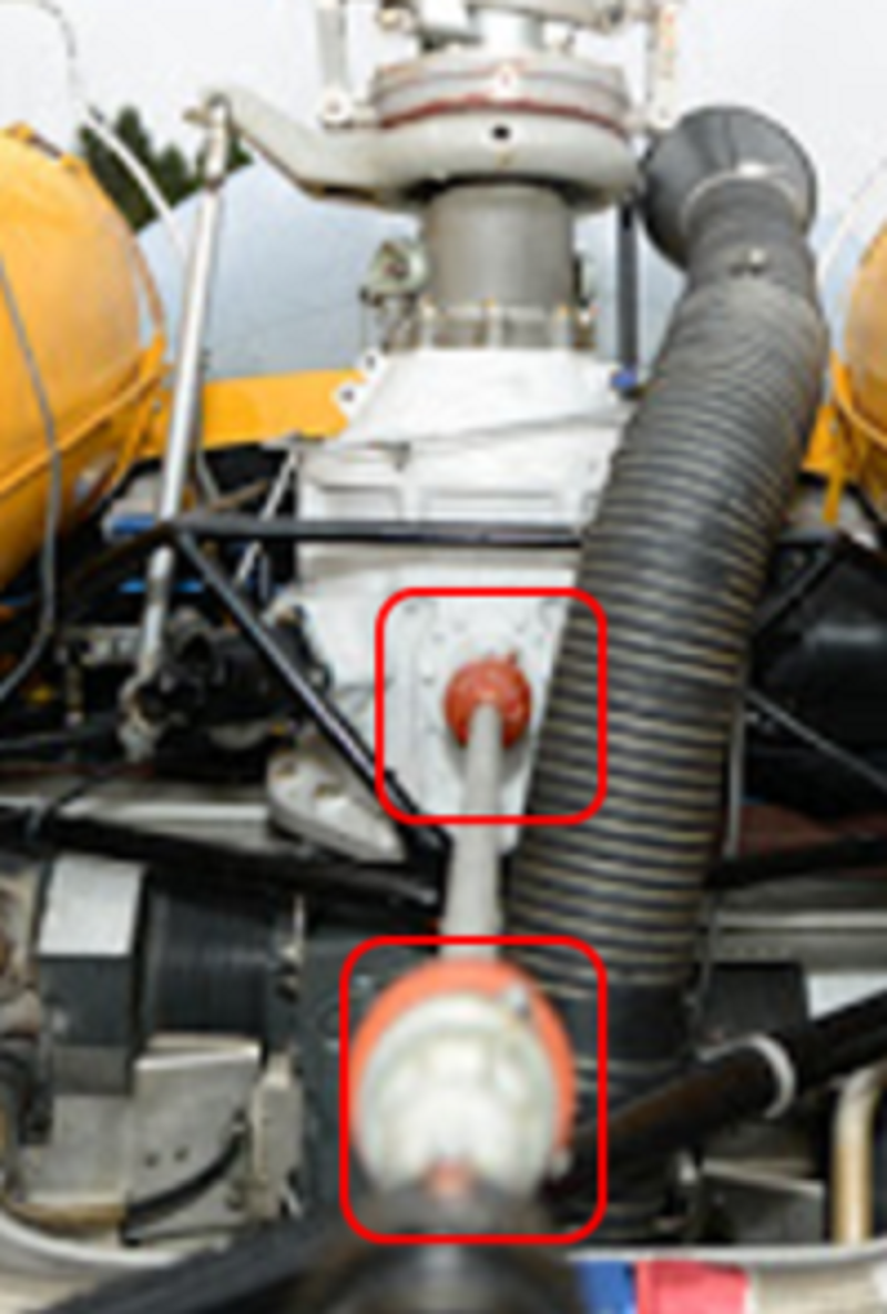
Which type of couplings does the Bell 47 use on the forward tail rotor drive shaft highlighted in the two red boxes?
Flexible curvic splined couplings
Flexible universal joint couplings
Flexible constant velocity joint coupling
Rigid couplings
What supports the center section of tail rotor driveshaft on the Bell 47?
Drive shaft dampers
A support tube with two bearings pressed inside
It has no supports the shaft spins freely
Several hanger bearing assemblies attached to the tail boom
How does the extension shaft inside the tail boom extension on the Bell 47 attach to the tail rotor (T/R) gearbox?
A universal joint coupling attached to the T/R
A splined end on the shaft where it attaches to the T/R
A Thomas coupling where it attaches to the T/R
A Curvic coupling assembly
What supports the extension shaft inside of the extension tube on the Bell 47 T/R driveshaft?
There is no support for the extension shaft
A single bearing supports the extension shaft in the center of the span
Two sets of bearings support the extension shaft inside the extension tube
There are six sets of hanger bearings supporting the extension shaft inside the extension tube
What does the Bell 47 pitch change drum and screw assembly, attached to the tail rotor gearbox, move to create T/R blade angle changes?
A threaded sleeve and Tee head attached to the blades through adjustable pitch links
A threaded nut and Dee tube attached to the blades through adjustable pitch links
A bellcrank assembly and pitch links attached to a sliding sleeve assembly
A bellcrank assembly and sliding rod assembly attached to a Tee head and pitch links
What is the type of gearing inside the Bell 47 T/R gearbox and what does it do?
Single stage planetary gears used to reduce the rpm and change the plane of rotation 90 degrees
Single stage helical bevel gears used to increase the rpm and change the plane of rotation 180 degrees
Single stage helical bevel gears used to increase the rpm and change the plane of rotation 90 degrees
Single stage helical bevel gears used to reduce the rpm and change the plane of rotation 90 degrees
What drives the T/R driveshaft on the Bell 206?
The output end of the Freewheeling unit on the main rotor transmission
The output end of the Freewheeling unit on the aft side of the engine gearbox
The output end of the Freewheeling unit on the combining gearbox
A dedicated drive pad on the lower portion of the main rotor Transmission
What is the forward short shaft on the T/R system made of and how are the flanges attached?
Aluminum alloy shaft has the flanges bonded to the ends of the shaft
Stainless steel shaft has the flanges bonded to the ends of the shaft
Stainless steel shaft has the flanges bonded and solid riveted to the ends of the shaft
Aluminum alloy shaft has the flanges bonded and solid riveted to the ends of the shaft
What is the purpose of the short shaft segment just between the forward and aft short shaft assemblies on the Bell 206 T/R drive system?
Drive the air conditioning compressor
Drive the oil pump for the main rotor transmission
Drive the engine oil pump
Drive the fan for the engine oil cooler
How does the Bell 206 transmission drive shaft assembly provide flexibility of the shaft as the tail boom deflects?
A universal joint coupling attached to the each end of the shaft
A splined end on the shaft where it attaches to both ends
A Thomas coupling where shaft segments attach to each other
A Curvic coupling assembly where each shaft segment attaches to each other
What is the purpose of indexing the Bell 206 flexible stainless steel plates on the driveshaft with flats spots on the opposite sides (180 degrees apart) of the circumference of round plate?
To reduce the weight of the plates
To identify and offset the grain patterns at 90 degrees for maximum flexibility during assembly
To identify and line up the grain patterns in the same direction for maximum flexibility
There are no indexing flats on the flexible plates
When using the beveled washers with the flexible plates on the Bell 206 driveshaft, which way do the bevels face and why?
Towards the head to prevent damage from the sharp edge of the washer on the head of the bolt
Towards the stainless steel plate to prevent damage from the sharp edge of the washer on the head of the bolt
Towards the stainless steel plate to prevent damage from the sharp edge of the washer on the plate
It doesn't matter which way the washer is installed, all washers are beveled on one side
What supports the center section of tail rotor driveshaft on the Bell 206?
Drive shaft dampers
A support tube with two bearings pressed inside
It has no supports the shaft spins freely
Several hanger bearing assemblies attached to the tail boom
What is the purpose of the shear pin located on the coupling flanges and splined plug inserts on the Bell 206 tail rotor drive shaft?
They are the primary fastener that prevents the flange or plug from rotating
They back-up the bonded joint on the flange or plug and shaft should the bonding fail
Their purpose is to shear if the tail rotor strikes something during operation
There are no pins installed on these coupling flanges and splined plugs they are all installed with solid rivets
How do you know if the bonding at one of the coupling flanges or splined plugs has failed?
The knurled headed shear pin will not be able to spin freely inside the fitting and shaft.
The tail rotor will turn independently free of the drive shaft
The tail rotor drive shaft will lock up and not be able to turn the tail rotor
The solid rivets will not spin freely inside the coupling flanges or splined plugs
What does the pitch change mechanism, attached to the tail rotor gearbox, move to create T/R blade angle changes on the Bell 206?
A threaded sleeve and Tee head attached to the blades through adjustable pitch links
A threaded nut and Dee tube attached to the blades through adjustable pitch links
A bellcrank assembly and pitch links attached to a sliding sleeve assembly
A bellcrank assembly and sliding rod assembly attached to a Tee head and pitch links
What is the type of gearing inside the Bell 206 T/R gearbox and what does it do?
Single stage planetary gears used to reduce the rpm and change the plane of rotation 90 degrees
Single stage helical bevel gears used to increase the rpm and change the plane of rotation 180 degrees
Single stage helical bevel gears used to reduce the rpm and change the plane of rotation 90 degrees
Single stage helical bevel gears used to increase the rpm and change the plane of rotation 90 degrees
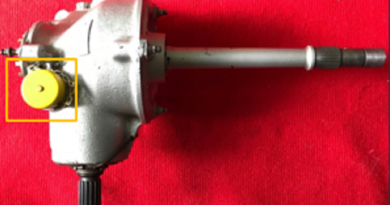
What is the purpose of the item illustrated in the diagram below with the amber box?
Sight gauge
Vented filler cap
Chip detector
Oil Pressure Switch
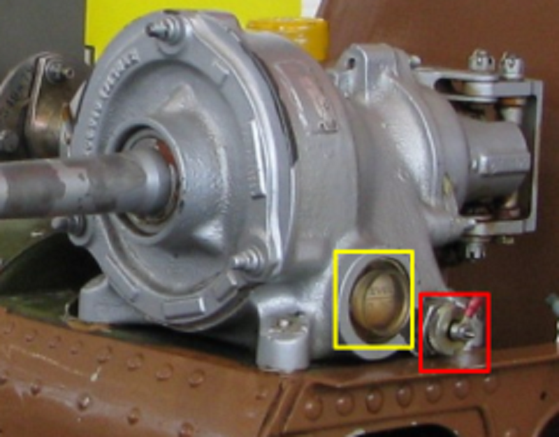
What is the purpose of the item illustrated in the diagram below with the red box?
Sight gauge
Vented filler cap
Chip detector
Oil Pressure Switch

What is the purpose of the item illustrated in the diagram below with the yellow box?
Sight gauge
Vented filler cap
Chip detector
Oil Pressure Switch
How many gearbox assemblies are installed on the Bell 212 Tail Rotor drive system?
0
1
2
3
How does the Bell 212 transmission drive shaft assembly provide flexibility of the shaft as the tail boom deflects?
A universal joint coupling attached to the each end of the shaft
A splined end on the shaft where it attaches to both ends
A Thomas coupling where shaft segments attach to each other
A Curvic coupling assembly where each shaft segment attaches to each other
What is the purpose of the gearbox located at the base or bottom of the tail fin on the Bell 212?
Change the plane of rotation 42 degrees and maintain the same speed of rotation
Change the plane of rotation 90 degrees and decrease the speed of rotation
Change the plane of rotation 90 degrees and maintain the same speed of rotation
Change the plane of rotation 42 degrees and decrease the speed of rotation
What is the type of gearing inside the Bell 212 T/R gearbox and what does it do?
Single stage planetary gears used to reduce the rpm and change the plane of rotation 90 degrees
Single stage helical bevel gears used to increase the rpm and change the plane of rotation 180 degrees
Single stage helical bevel gears used to reduce the rpm and change the plane of rotation 90 degrees
Single stage helical bevel gears used to increase the rpm and change the plane of rotation 90 degrees
How does the Hughes 500 Tail Rotor drive shaft assembly limit flexibility of the shaft?
A universal joint coupling attached to the each end of the shaft
A drive shaft damper assembly attached mid-way along the span of the shaft
A Thomas coupling where shaft segments attach to each other
A Curvic coupling assembly where each shaft segment attaches to each other
What is the type of gearing inside the Hughes T/R gearbox and what does it do?
Single stage planetary gears used to reduce the rpm and change the plane of rotation 90 degrees
Single stage helical bevel gears used to increase the rpm and change the plane of rotation 180 degrees
Single stage helical bevel gears used to reduce the rpm and change the plane of rotation 90 degrees
Single stage helical bevel gears used to increase the rpm and change the plane of rotation 90 degrees
How does the AS355 transmission drive shaft assembly provide flexibility of the shaft as the tail boom deflects?
A universal joint coupling attached to the each end of the shaft
A Flector coupling where shaft segments attach to each other
A Thomas coupling where shaft segments attach to each other
A Curvic coupling assembly where each shaft segment attaches to each other
What drives the T/R driveshaft on the ES355?
The output end of the Freewheeling unit on the main rotor transmission
The output end of the Freewheeling unit on the aft side of the engine gearbox
The aft end of the output on the combining gearbox
A dedicated drive pad on the lower portion of the main rotor Transmission
Which type of couplings does the Bell 47 use on the forward tail rotor drive shaft?
Rigid couplings
Flexible constant velocity joint coupling
Flexible curvic splined couplings
Flexible universal joint couplings
How does the Bell 206 transmission drive shaft assembly provide flexibility of the shaft as the tail boom deflects?
A universal joint coupling attached to the each end of the shaft
A splined end on the shaft where it attaches to both ends
A Curvic coupling assembly where each shaft segment attaches to each other
A Thomas coupling where shaft segments attach to each other
What is the type of gearing inside the Bell 206 T/R gearbox and what does it do?
Single stage planetary gears used to reduce the rpm and change the plane of rotation 90 degrees
Single stage helical bevel gears used to increase the rpm and change the plane of rotation 180 degrees
Single stage helical bevel gears used to reduce the rpm and change the plane of rotation 90 degrees
Single stage helical bevel gears used to increase the rpm and change the plane of rotation 90 degrees
What is the purpose of the gearbox located at the base or bottom of the tail fin?
Change the plane of rotation 90 degrees and decrease the speed of rotation
Change the plane of rotation 42 degrees and maintain the same speed of rotation
Change the plane of rotation 42 degrees and decrease the speed of rotation
Change the plane of rotation 90 degrees and maintain the same speed of rotation
How does the Hughes 500 transmission drive shaft assembly limit flexibility of the shaft?
A universal joint coupling attached to the each end of the shaft
A drive shaft damper assembly attached mid-way along the span of the shaft
A Thomas coupling where shaft segments attach to each other
A Curvic coupling assembly where each shaft segment attaches to each other
During an autorotation decent with the collective full down, what direction is the airflow through the main rotor system?
Up through the blades from the bottom to the top
Up through the blades from the top to the bottom
Down through the blades from the top to the bottom
Down through the blades from the bottom to the top
What is the purpose of an autorotation?
To allow the pilot to land the helicopter safely with no engine power
To allow the pilot to land helicopter safely under full engine power
To ensure that the helicopter rotor system automatically tilts forward as the cyclic is pushed forward
To ensure that the various components are rotated through the correct duty cycle during maintenance activities
According to the instructions for Autorotation Test Flights, which of the following is NOT one of the three pieces of information are required to be recorded during the Autorotation Decent?
N1 Tachometer Reading during the procedure
Nr Tachometer Reading during the procedure
Outside Air Temperature at the start of the procedure
Altimeter Reading at the start of the procedure
During the Autorotation Speed Calculation, which of the following is NOT one of the three parameters that you require to determine if the rotor RPM is correct based upon the Autorotation Chart?
Direction and speed of the wind at take-off
Select appropriate column based on the density altitude
Compare Autorotation RPM to range on chart to confirm correct rigging
Adjust main rotor head pitch change links to increase or decrease rpm as applicable
Following the completion of an autorotation test flight you discover the Nr is 488 RPM and the range is 480 rpm to 485 rpm. What is the required rectification?
Slow rotor speed by increasing blade pitch
Slow rotor speed by decreasing blade pitch
Increase rotor speed by increasing blade pitch
Increase rotor speed by decreasing blade pitch
Following the completion of an autorotation test flight you discover the Nr is 488 RPM and the range is 490 rpm to 505 rpm. What is the required rectification?
Increase rotor speed by decreasing blade pitch
Increase rotor speed by increasing blade pitch
Slow rotor speed by decreasing blade pitch
Slow rotor speed by increasing blade pitch
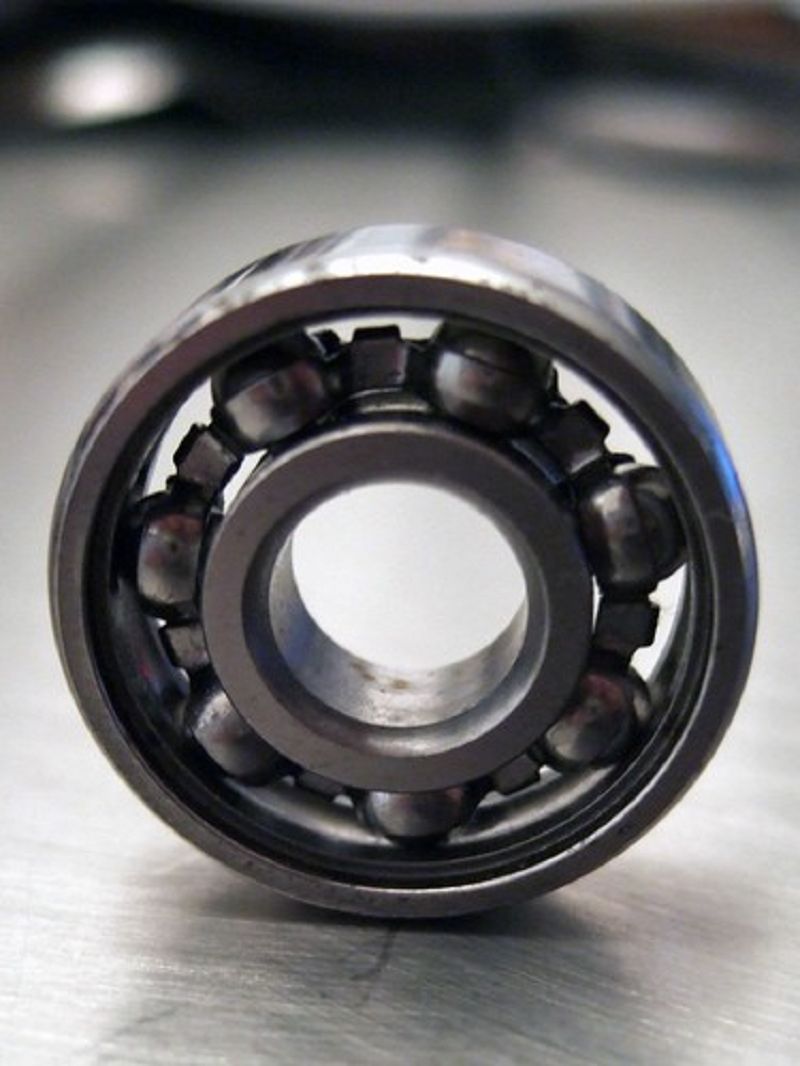
What type of bearing is this?
Ball bearing
Thrust type
Plane Bearing
Roller Bearing
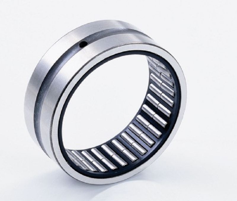
What type of bearing is this?
Roller Bearing
Plane bearing
Ball Bearing
Thrust type
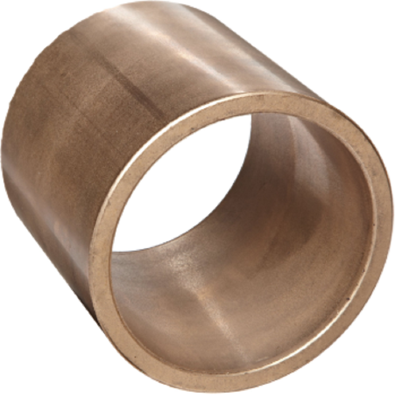
What type of bearing is this?
Plane bearing
Thrust type
Roller Bearing
Ball bearing
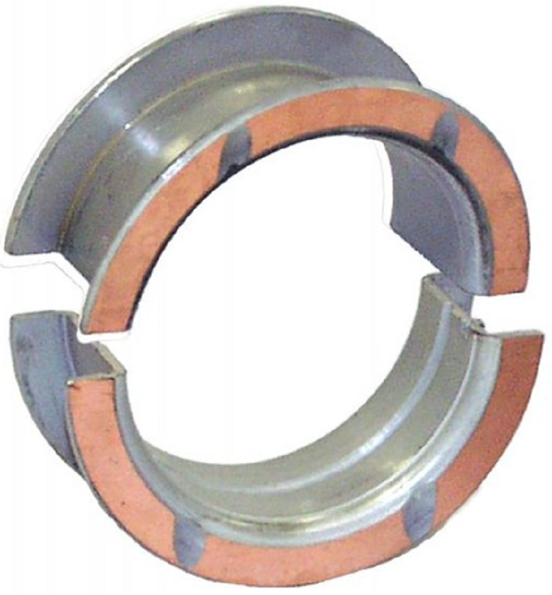
What type of bearing is this?
Thrust type
Plane bearing
Roller Bearing
Ball bearing
{"name":"Rotary Week 4 Review", "url":"https://www.quiz-maker.com/QPREVIEW","txt":"What is the purpose of the tail rotor system?, What is the purpose of the tail rotor system?, Which of the following is NOT one of the standard requirements of the system driving the tail rotor?","img":"https://www.quiz-maker.com/3012/CDN/93-4564254/flexible-curvic-splined-couplings.png?sz=1200"}
More Quizzes
Easements
13613
Gintama Anime Quiz
116204
Esame etnostoria
52260
Che tipo di Mamma sei?
10511
Soccer Ball Knowledge - Free Online Challenge
201018214
Cogito Ergo Sum - Free Philosophy Test Questions
201019249
Cytology with Answers - Free Interpretive Cases
15817648
Zombie Apocalypse: Which Survivor Are You?
201016538
Mental Age Test - Take It Free Online
201016538
Classic Rock Trivia - Free to Test Your Knowledge
201016538
Who Is My Spirit Guide - Discover Yours Free
201017255
Killjoy Name Generator - Free & Instant Results
201017067