AMP_RC_T.SHOT_PWM

Understanding Push-Pull Amplifiers Quiz
Test your knowledge of push-pull amplifiers and their properties with this comprehensive quiz! Designed for enthusiasts and students alike, this quiz will challenge your understanding of circuits, amplifier classes, and various coupling methods.
Topics covered include:
- Amplifier classes (A, B, AB)
- Crossover distortion
- Transformer coupling
- Coupling methods (RC, direct, transformer)
The push-pull circuit needs two signals that are _____
in phase and equal in magnitude
in phase and unequal in magnitude
180° out of phase and equal in magnitude
180° out of phase and unequal in magnitude
What should be there at the circuit input to obtain the signals mentioned in the previous question?
a phase splitter circuit
a transformer with a center tap
a transformer without a center tap
Either a. Or b.
The crossover distortion in the procedure was caused by _____
an increase in the amplitude of the input signal
The removal of the dc bias of the circuit.
An increase in total de circuit current.
The removal of the center tap of transformer T
If class B amplifiers dissipate less power than class AB amplifiers, why do some push-pull circuits use class AB amplifiers?
Two class AB amplifiers require a smaller dc power supply
Two class B amplifiers can cause distortion at the zero crossing
Class B amplifiers cannot be used back-to-back
Class AB amplifiers have a lower base-emitter voltage drop
If the ac input signal (Vi) is zero for the class AB push-pull circuit, the ac base _____
currents of both Q1 and Q2 are zero
Current of Q1 is zero
current of Q2 is zero
Currents of both Q1 and Q2 are equal to the dc base currents
How are the two transistors in a push-pull class AB circuit biased?
They are in the center of the load line
One is near cut-off, the other is near saturation
They are both near cut-off
They are both near saturation
If the dc bias is removed from a push-pull class AB circuit, _____
the output goes to zero volts
The peaks and valleys of the output will be clipped
cross-over distortion occurs
None of the above.
In a class AB push-pull amplifier, voltage gain _____
Is high and power gain is low
Is low and power gain is high
and power gain are high
and power gain are low
For how many degrees of the input signal a class AB amplifier conducts ?
90° or less
between 90° and 180°
between 180° and 360°
almost 360°
The output transformer in a push-pull amplifier _____
combines the two collector signals into one output signal
matches the circuit to the low impedance load
furnishes a dc path for the collector supply voltage
All of the above
The maximum efficiency of resistance loaded class A power amplifier is _____
5%
50%
30%
25%
In class A operation, the operating point is generally located at _____ point of the DC load line
cut off
the middle
saturation
any point
What turn ratio (Np/Ns) of transformer is required to match 2 Ω speaker to a transistor having an output impedance of 301 Ω? HINT: RL`=Ratio^2*RL
36
20
15
6.12
_____ coupling is generally employed in power amplifiers
Transformer
RC
direct
Impedance
A BJT class B push-pull amplifier with no transformer coupling uses
two NPN transistors
two PNP transistors
complementary transistors
none of these
Crossover distortion is a problem for _____
class A amplifiers
class AB amplifiers
class B amplifiers
Common-base amplifiers
The maximum efficiency of a class B push-pull amplifier is _____
25%
50%
79%
98%
The maximum efficiency of a class AB amplifier is _____
higher than a class B
the same as a class B
about the same as a class A
Slightly less than a class B
RC coupling is used for … Amplification*
Voltage
Current
Power
None of the above
The use of a by-pass capacitor in CE amplifier is …*
To increase voltage gain
To increase negative feedback
For decreasing the frequency
To block dc
The desired input impedance of a transistor is ...*
Low
Very low
High
Very high
The phase difference between the output and the input voltage of a CE amplifier is ...*
180
360
90
0
The purpose of capacitors in a transistor amplifier is ...*
To protect the transistor
To cool the transistor
To couple or bypass ac component
To provide biasing
In an RC coupling scheme, the coupling capacitor CC must be large enough .....*
To pass DC between the stages
Not to attenuate the low frequencies
To dissipate high power
None of the above
The purpose of RC or transformer coupling is ...*
Block AC
Separate bias of one stage from another
Increase thermal stability
None of the above
Transformer coupling is used for …. amplification*
Current
Voltage
Power
None of the above
If a three-stage amplifier has individual stage gains of 10db, 6db and 15db; then the total gain in dB is*
600dbB
24dB
14dB
31dB
The cascading of two transistor amplifiers implies...*
Output of first stage sent to input of second stage
Output of first stage sent to coupling device
Input of first stage sent to input of second stage
None of the above
The reason why RC coupling is not used to amplify extremely low frequencies is ...*
There is considerable power loss
Electrical size of coupling capacitor becomes very large
There is a hum in the output
Electrical size of coupling capacitor becomes very small
�……….. Coupling provides the maximum voltage gain*
RC
Transformer
Direct
Impendence
RC coupling is generally confined to low power applications because of ………*
Large value of coupling capacitor
Low efficiency
Large number of components
None of the above
The bandwidth of a single stage amplifier is …………. That of a multistage amplifier*
More than
The same
Less than
other
An advantage of RC scheme is ..*
Good matching
Economy
High efficiency
None of the above
In PWM, the ______ of pulse width modulator is varied and controlled by the input audio signal amplitude.*
Amplitude
position
width
none of the above
In PPM, the ______ of pulse width modulator is varied and controlled by the input audio signal amplitude.*
Amplitude
position
width
none of the above
In PWM, as the amplitude of the audio signal is increasing the pulse width will become ________.*
narrower
wider
fixed
none of the above
In PAM, the ______ of pulse width modulator is varied and controlled by the input audio signal amplitude.*
Amplitude
position
width
none of the above

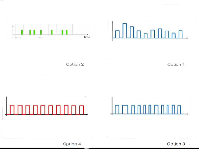
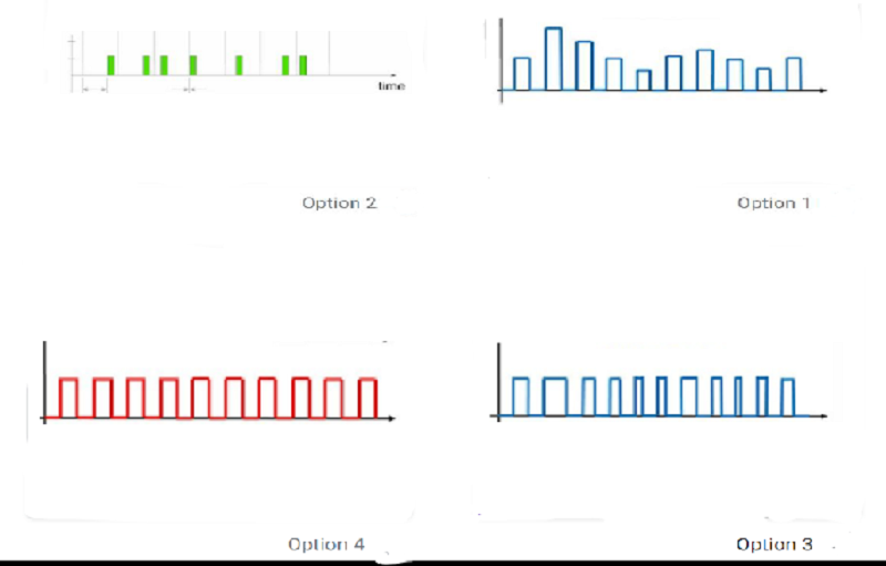
Which of the figures represent PWM*
Option 1
Option 2
Option 3
Option 4
What is the usage of the first LM555 in LM555 PWM circuit*
Astable multivibrator
Monostable multivibrator
Stable multivibrator
None of the above
What is the usage of the second LM555 in LM555 PWM circuit*
Astable multivibrator
Monostable multivibrator
Stable multivibrator
None of the above
Period of Astable multivibrator waveform is*
.693 (R_1+R_2 ) C_1
.693 (R_1+2R_2 ) C_1
.693 (R_2 ) C_1
(R_1 ) C_1
In product detector PWM demodulator, the multiplication circuit is followed by*
Low pass filter
High pass filter
Band pass filter
Band reject filter
In UA741 PWM, what is the usage of OPAMP?*
Inverter amplifier
Non-Inverting amplifier
Comparator
adder

In UA741 PWM circuit, if the input terminal is grounded, what is the output found in the output terminal*
Option 1
Option 2
Option 3
Option 4
MC1496 PWM demodulator circuit base idea is*
convert to PAM signal and demodulate
convert to PPM signal and demodulate
product detector
none of the above
Pulse width of Monostable multivibrator is*
.693 (R_1+R_2 ) C_1
.693 (R_1+2R_2 ) C_1
.693 (R_2 ) C_1
1.1 (R_1 ) C_1
What are the functions of VR1 in UA741 PWM circuit?*
Control reference voltage of comparator
Control negative feedback voltage
a charge/discharge path
none of the above
LM555 can be used in constructing a _________*
Astable multivibrator
Monostable multivibrator
Stable multivibrator
All the above
{"name":"AMP_RC_T.SHOT_PWM", "url":"https://www.quiz-maker.com/QPREVIEW","txt":"Test your knowledge of push-pull amplifiers and their properties with this comprehensive quiz! Designed for enthusiasts and students alike, this quiz will challenge your understanding of circuits, amplifier classes, and various coupling methods.Topics covered include:Amplifier classes (A, B, AB)Crossover distortionTransformer couplingCoupling methods (RC, direct, transformer)","img":"https:/images/course5.png"}
More Quizzes
VLSI Design - Quiz
10538
Elec_competition_4.13.22
10521
The ultimate Virat Kohli quiz
1050
Regras Rvv
5270
Quiz-76 Challenge: Ultimate Philadelphia 76ers Trivia
201041029
Free Anatomy and Radiology Knowledge Test
201022797
Free Geriatric Nursing Knowledge Test
201026079
Free Golf Trivia & Preference
201022625
Test Your French Objective Pronouns: Free Challenge
201038397
Ultimate iCarly: Are You a True Superfan?
201046792
Free Economics Demand and Supply
201028825
Free Data Visualization Knowledge
201027929